Precision Horology
Q3 SENSORS


There were two types of “sensing” that had to be used in Q3, the sensors that actually caused impulse to be applied to the pendulum and the sensors that determined when each pendulum actually received the impulse.
Below each pendulum there is a small laser assembly that is mounted in an adjustable
holder assembly. Although the lasers are mounted horizontally, a prism and lens assembly
changes the direction of the beam so that it emerges in a tightly focused vertical
beam. Each laser assembly is mounted so that the quartz pendulum rod passes over
it. The bottom of the pendulum rod is polished and fitted with a tiny aperture so
that when the pendulum rod passes over the laser at its exact center, the laser beam
shoots up the pendulum rod. The top of the pendulum rod is also polished and fitted
with a simple plano-
The very simple logic that determines which direction to impulse each pendulum is controlled by four photocell assemblies mounted on the movement. The impulse arms which are fitted to the pendulum rod holder assemblies have small vertical blades attached that act as interrupters to the photocells. They control the logic that determines which pendulum is impulsed and in what direction. I originally tried to use hall effect devices to do this but there wasn’t enough movement of the impulse arms to overcome the hysteresis effect and they proved to be very unreliable. The photocell system works particularly well and has had no problems.
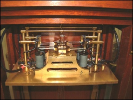
The completed unfinished test movement fitted
fitted into the case. You can see
the quartz impulse arms, the coils and the blades that operate the photocells.
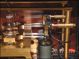
A closeup of the adjustable photocell assemblies and the operating blades attached to the quartz arms.
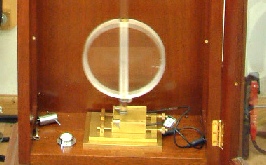
Beneath the two quartz pendulum bobs, the
assembly holding the two laser modules. They are adjustable front to back and left to right so the laser beam hits the quartz pendulum rod
exactly as it passes the center of its swing.
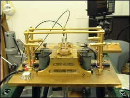
The original test movement with hall effect devices instead of the photocell assemblies. It proved impractical.