Precision Horology


CONSTANT FORCE ESCAPEMENT CLOCK Q2

After I had finished Q1, I wanted to make something smaller and a little less ambitious. I felt that a table clock would be a little more practical than Q1 but I wanted it to be fairly accurate and attractive. It had to be interesting to watch and within my capabilities as a dilettante machinist. I like clocks that are seconds beating and decided that a compound pendulum would be appropriate to keep the size reasonable and still beat seconds. Although compound pendulums generally have a bad reputation and it ’s commonly thought that they are less accurate than conventional pendulums, theoretically they are just as accurate and if left undisturbed should perform as well as a conventional pendulum with the same characteristics. I decided to mount the clock under a glass dome and run it in a partial vacuum to alleviate the problems
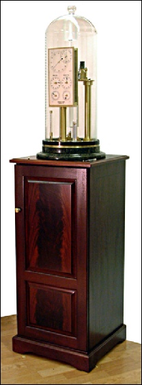
of barometric compensation. The bobs and pendulum rod are made of fused quartz. After calculating the thethoretical length of the pendulums, I had a dome made approximately 27" high and 11" in diameter to house everything I needed. I wanted to use some form of constant force impulsing with electromagnetic control and designed a scheme in which small "hammers" of known fixed weight are dropped alternately on pallets that are fixed to the pendulum rod at the fulcrum of the suspension support. I built an experimental model to see how it would work and found that with only a little modification it would perform well.
The base of the clock is made of marble and the cabinet is mahogany with flame panels. The power supply and logic board as well as the vacuum pump are contained in the cabinet.
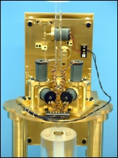
(RIGHT) The back of the finished
movement.
The marble base, the blown glass dome and the mahogany cabinet were custom made for Q2.

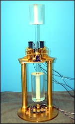
(LEFT) A test of the completed mechanical part of the movement from the front before the dial was made.
It’s a fairly large file so you should have a dsl connection at least.