Precision Horology
Q3 IMPULSE


Each pendulum rod is mounted in a gimbal type holder which has arms attached to it
that are perpendicular to the pendulum rods and knife edges. These perpendicular
rods – a pair on either side of each pendulum rod -
Below each pendulum there is a small laser assembly that is mounted in an adjustable
holder assembly. Although the lasers are mounted horizontally, a prism and lens assembly
changes the direction of the beam so that it emerges in a tightly focused vertical
beam. Each laser assembly is mounted so that the quartz pendulum rod passes over
it. The bottom of the pendulum rod is polished and fitted with a tiny aperture so
that when the pendulum rod passes over the laser at its exact center, the laser beam
shoots up the pendulum rod. The top of the pendulum rod is also polished and fitted
with a simple plano-
to the photocells. They control the logic that determines which of the pendulums is given impulse and in what direction.
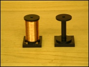
A core and an unfinished wound coil. I machined the forms with an integral mounting base.
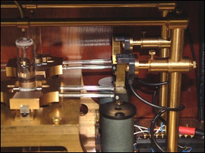
You can clearly see the quartz arms attached to the pendulum rod gimbals. Magnets affixed to the impulse arms sit above the coils. The photocell interruptor blades sit above the magnets.
The laser assembly. The adjustment micrometers on the right side are biased by the springs in the left. The prisms change the horizontal beam to vertical.
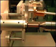
One of the impulse coils being wound.
The CNC coil winding machine which can automatically wind any size coil.
The two pendulums in the test setup in a check of the laser lenses.