
Precision Horology
Q3 PENDULUMS
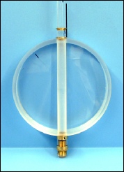

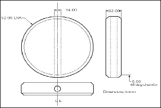
Both the pendulum rods and pendulum bobs are made of fused quartz. The pendulum bobs are 152 mm in diameter (approximately 6”) with a 45 degree chamfer and the thickness is 32 mm (approximately 1.25”). They are drilled through the diameter to accommodate the 14mm rod.
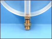
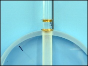
There were a couple of problems that had to be addressed: how to adjust the bob on the rod, and how to keep the bob from twisting on the rod. In order to be able to adjust the bob, I made a very thin, finely threaded tube to fit over the bottom of the pendulum rod. I drilled a small hole through the rod and fastened the threaded tube to the rod. A matching knurled nut was made to accommodate the threaded tube and connected to the bottom of the pendulum bob through a short piece of quartz tubing. In order to keep the bob from twisting on the pendulum rod, I made a pair of thin brass ferrules, one to fasten to the top of the pendulum bob and one to fasten to the pendulum rod. I connected them with a short piece of steel vertically mounted to the top of the pendulum ferrule and going through a slot in the ferrule mounted on the rod. The pendulum can be moved up or down to adjust but cannot twist using this arrangement.
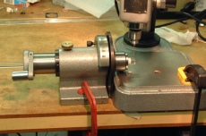
Drilling the quartz rods didn’t prove to be too much of a problem. I mounted the rods in an indexing device using an oversize collet to accommodate tape that I wrapped around the rod in order to protect it. The rods must be supported at the back end. The indexer permitted me to drill from both sides in order not to chip the rod when breaking through one side. I used diamond drills with plenty of lubricant and I was able to make good clean, sharp holes through the quartz.
The entire pendulum quartz assembly. The ant-
The bottom of the bob showing the threaded rod and knurled adjusting. The spacer under the bob is quartz tubing
Top of the pendulum bob showing the anti twist device.
(BELOW) The quartz rod drilling setup consisting of a miniature high speed drill press and an indexing device
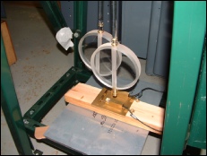
The pair of pendulums running under test.
You can see the adjusting mechanism under the pendulum rods containing the lasers.
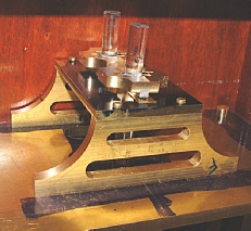
The test assembly for the quartz pendulum rod. The rod sits in a gimbal like device so that it automatically levels the pendulum
The pair of rods in the test bed.
(RIGHT) A drawing of the quartz pendulum bob. I had a shop that specializes in quartz machining make the bob for me.