Precision Horology
SENSORS
I had over the years, experimented with various kinds of sensors. I’ve used photocells, capacitive sensing and proximity sensing devices in various clocks more or less successfully. Although I never used Hall Effect (HE) devices in any of my earlier clock efforts, I liked the idea that they were relatively easy to use and quite stable. I settled on using an Allegro type UGQ5140K HE sensor and solenoid driver. The driver (an amazing .9 amps) was built into the small package and would be capable of driving the clock directly if I wanted to. I decided not to drive the clock from the HE device but used it to drive the logic board relays that operated the clock. I used very small cobalt magnets fastened to the fused quartz pendulum rod just above the lower pendulum bob to activate the HE devices. In discussions I had with the applications engineers at Allegro, I was assured the the HE devices were very stable, and each individual unit had magnetic operate and release points that would not perceptibly change as long as the temperature was held within a couple of degrees. I verified this by setting up an HE device in the quill of my mill and mounted a cobalt magnet on a fixture attached to the table. Moving the mill table and using the DRO (capable of measuring to .0001”) I checked the turn on and turn off points of several of the HE devices and found that (after about 100 trials) I couldn’t see any meaningful variation in the operating points. I felt that the HE devices would be excellent sensors for my use.
I mounted the HE assemblies on a vertical fused quartz rod which was fixed to the base plate at the same height as the suspension and running parallel to the pendulum rod. I did this so that any vertical movement of the sensors because of temperature variation would equal that of the pendulum rod and the relationships between the magnet and sensors would not change.
The choice of magnets was also important here. Originally, I had planned to use neodymium magnets because of their strong field. I settled on cobalt however because it had a much better temperature vs field coefficient of temperature.
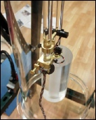
(1) The photograph taken from above the lower pendulum bob shows the upper logic sensors and the lower impulse sensor. You can see the vernier that controls the horizontal position of the impulse sensor in relation to the pendulum rod. This sensor is mounted on a small quartz rod.
(2) In this view the vertical parallel fused quartz rod that holds the sensors can be clearly seen as well as the vernier controlled quartz rod holding the HE sensor. The sensor can also be adjusted vertically. The black disc at the bottom of the rod is there just to hold all of the wires in place so they don’t interfere with the pendulum bob.
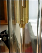
(3) A closeup from the left side shows the HE devices in their sockets a bit more
clearly.
(4) Another view from the right side of the pendulum.
(5) The stabilizer for the quartz rod holding the sensors. It was designed so that the rod would not vibrate. The fingers hold the rod firmly but permit the rod to contract and expand with temperature.
1
2
3
4
5


